How to Properly Repair FCS16 RIP-R-STRIPPER® Tile Stripper Extension Cords | Issue No. 21

How to Properly Repair FCS16 RIP-R-STRIPPER® Tile Stripper Extension Cords
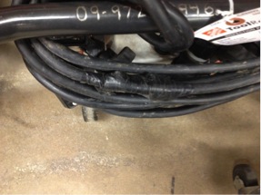
FIGURE 1. Improperly repaired

FIGURE 1. Improperly repaired

FCS16-1000A Extension Cord used with the FCS16 RIP-R-STRIPPER Tile Stripper improperly repaired. FIGURE 1.

In this case, it is presumed the RIP-R-STRIPPER Blade had come in contact with the extension cord and accidently cut it. Unfortunately, the Technician did not repair the cord according to National Electric Code practices by using the electrical tape. A replacement extension cord is expensive and you can save money by properly repairing a damaged cord.

 Need help?
Call us at 800.533.0524, or
email: support@generalequip.com.

Improper electrical cable splicing techniques can result in property damage and /or personal injury!


It is not legal to splice electrical extension cords.
Even if you solder the wire, wrap each wire with electrical tape and encase the whole splice in heat shrinkable tubing, it still will not have the abrasion resistance of a new cord. Plus, this practice is not permitted under the National Electric Code.
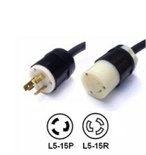
FIGURE 2.

FIGURE 2.

Instead, install a high quality NEMA L5-15P locking male plug and NEMA L5-15R locking female receptacle to the cut/severed extension cordends. These devices have a twist lock feature which will prevent them from separating when the extension cord is pulled around during normal tile stripping job applications. A typical NEMA L5-15P Locking Male Plug and a typical NEMA L5-15R Locking Female Receptacle are both depicted in FIGURE 2.

These electrical cable connecting devices are readily available in the field. Follow the installation instructions provided. Not using devices with the twist lock feature will allow the plug and receptacle to separate as the RIP-R-STRIPPER moves around on the jobsite.


Always follow repair procedures as specified by the current National Electric Code. Remember…safety is everyone’s responsibility!


If you have any questions or comments, please feel free to contact us.
Telephone: 800.533.0524 | Email: support@generalequip.com

Improper Throttle Cable Installation for the Two Man Auger | Issue No. 20

Improper Throttle Cable Installation for the Two Man Auger

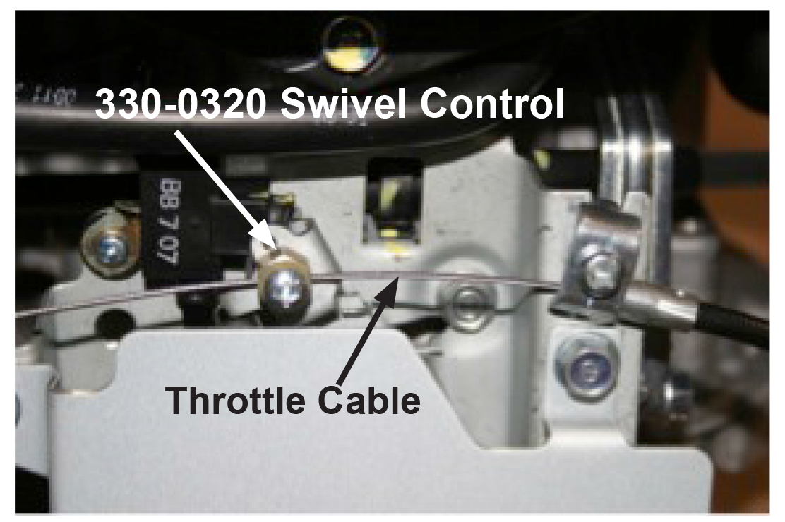
Improper throttle cable install can increase the potential for personal injury. FIGURE 1.

The throttle cable installation depicted will significantly reduce operator control while using the twist grip throttle system and could directly contribute to personal injury.

  1. Extended use of this installation can allow the throttle cable to be severed by the carburetor throttle mechanism leading and could directly contribute to personal injury.
  2. Correct installation will position and secure the Part Number 330-0320 Swivel Assembly in the hole provided on the carburetor throttle mechanism. The 330-0320 Swivel Control is designed to rotate as necessary to minimize throttle cable wear and provide for enhanced operator control. FIGURE 2.

To help reduce the potential for personal injury, it is critical for all throttle mechanism components be properly installed and maintained. The throttle control system must be inspected every time the Two Man Auger is turned. Refer to the applicable Tool Turning Tips publication for additional information. http://www.generalequip.com/Library. Form: GEF16101202.

Check your General hole digging equipment TODAY and every time tools are rented to determine the throttle cable is properly installed as outlined in the appropriate Operator Manual. Have questions or need help? Contact our Customer Service Department for assistance. 1.800.533.0524 or sales@generalequip.com

Remember: Safety is everyone’s responsibility!

Need help?
Call us at 800.533.0524, or
email: support@generalequip.com.

FIGURE 1. Improper Install

eHelp20p_ImgB

FIGURE 2. Proper Install

 If you have any questions or comments, please feel free to contact us.
Telephone: 800.533.0524 | Email: support@generalequip.com

How do you check the transmission oil level in 300 Series Hole Diggers? | Issue No. 16

Questions: How do you check the transmission oil level in 300 Series Hole Diggers?

Answer: Follow procedure in the Operator Manual.

 
Note: This information applies only to the General 330H, 343H and 357H Hole Diggers.
 

CAUTION!
300 Series Hole Diggers are shipped from the factory without oil in the transmission. Oil is provided in the original shipping carton. Failure to properly fill and operate the transmission with oil can result in damage that is not covered by the product warranty program.

Need help?
Call us at 800.533.0524, or
email: support@generalequip.com.

Steps below to check oil level.

  1. Do not check oil level with the engine running!

  2. Place the Hole Digger on a level surface.

  3. Wipe any dust or dirt from the transmission oil filler/level plug area.

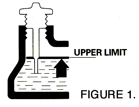
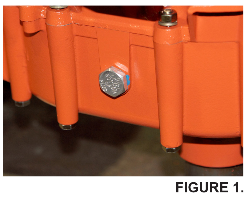
    The oil filler/level plug is located on the side of the transmission. FIGURE 1.

    300TranOil1

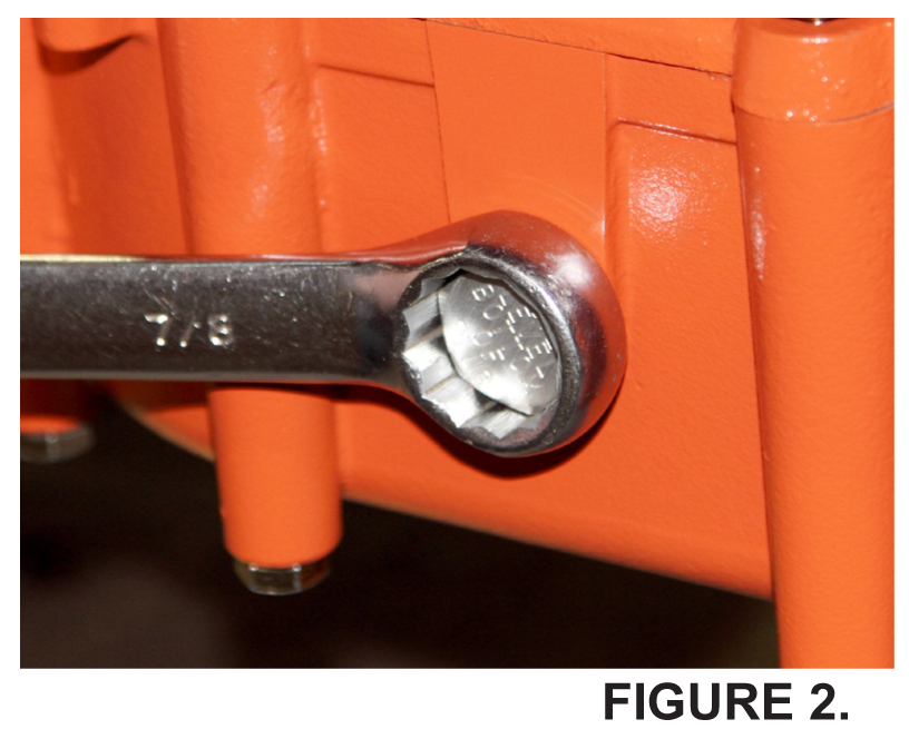
  4. Remove the plug with a suitable wrench. FIGURE 2.

    300TranOil2

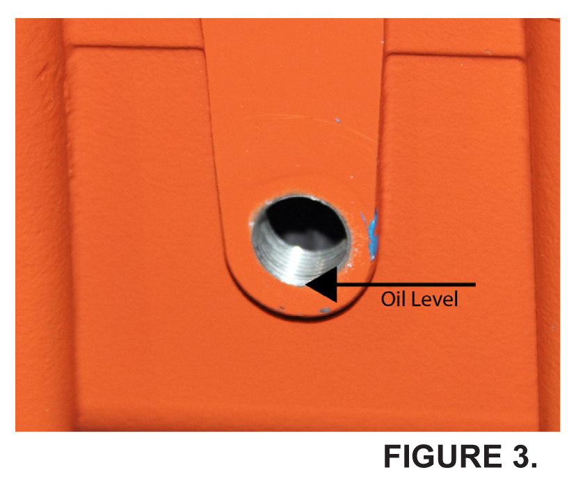
  5. The transmission oil level is to be maintained at the bottom of the oil filler/level plug hole. FIGURE 3.

    300TranOil3

  6. If the oil level is not visible add oil up to bottom of the hole. DO NOT OVERFILL.

  7. Allow excess oil to drain out of the transmission if overfilled.

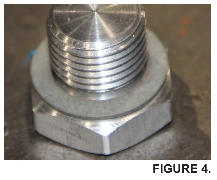
  8. Inspect the oil fill plug gasket for proper security. If necessary, replace the gasket with a factory approved replacement part only. FIGURE 4.

    300TranOil4

  9. Reinstall the oil filler/level plug. Tighten securely with a suitable wrench. FIGURE 2.

  10. Wipe off any excess spilled oil. Properly dispose of any spilled oil.

 CAUTION!
Correct oil level is important to insure proper centrifugal clutch operation. Excessive oil level will cause excessive clutch slippage. Low oil level will cause improper lubrication. Both conditions will cause high operating temperatures that will reduce service life and affect digging performance. Service related problems as a result of improper transmission lubrication are not covered by the product warranty program.


Transmission Oil Capacity: 1 US quart (.94 l)
Transmission Oil Type: SAE 10W30, SAE 30 Detergent, conforming to API Classification SJ or later
Consult the Operator Manual for additional information.

To download the Operator Manual, Click or copy and paste the
URL: http://www.generalequip.com/prod_library/267-item.pdf into a browser.


 If you have any questions or comments, please feel free to contact us.
Telephone: 800.533.0524 | Email: support@generalequip.com
Correct Method to Check Oil Level for the Honda GXV140 and GXV160 Engine? | Issue No. 15

Questions: What is the Correct Method to Check Oil Level for the Honda GXV140 and GXV160 Engine?

Answer: Check According to the Honda Developed Procedure.

 
Note: This eHelp! only applies to the General 330H, 343H and 357H Hole Digger powered by the Honda GXV140 and GXV160 engines!
 
Filling the engine crankcase with oil will require a level working platform of sufficient size and appropriate height. As an alternative, the transmission driveshaft can be securely in a suitable bench vise.
 

CAUTION:
Running the engine with insufficient oil can cause serious engine damage.

Need help?
Call us at 800.533.0524, or
email: support@generalequip.com.

Steps below to check oil level.

  1. Do not check oil level with the engine running!
  2. Place the Hole Digger on a level surface.
  3. Wipe any dust or dirt from the crankcase dipstick/filler plug area.
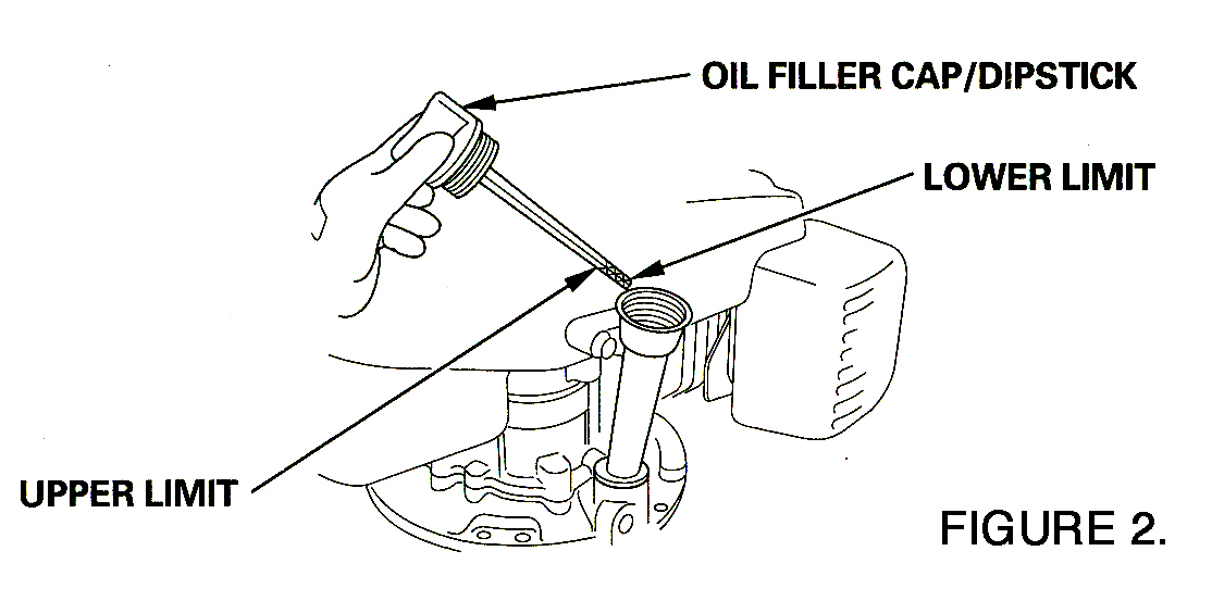
  4. Remove the oil filler cap/dipstick and wipe clean.
  5. Insert the oil filler cap/dipstick into the oil filler neck as shown, but do not screw it in. Remove it to check the oil level. FIGURE 1.

    GXV160_Oil2

  6. If the oil level is near or below the lower limit mark on the dipstick, fill with the
    recommended oil to the upper limit mark, DO NOT OVERFILL. FIGURE 2

    GXV160_Oil1

  7. Screw in the filler cap/dipstick securely. Wipe off any excess spilled oil. Properly dispose of any spilled oil.


WARRINING:
Failure to follow correct procedures can give an inaccurate oil level reading.


The correct oil capacity for the Honda GXV160 engine is .65 Liter or 23 US fluid ounces. Refer to the Owner’s Manual supplied by Honda for additional information including type and weight. Service related problems as a result of improperly filling the engine with oil are NOT covered by the Honda warranty program.

To download the Honda Owner’s Manual, (for the GXV160 engine), type or copy and paste the
URL: http://engines.honda.com/pdf/manuals/31ZE6030.pdf into a browser.


 If you have any questions or comments, please feel free to contact us.
Telephone: 800.533.0524 | Email: support@generalequip.com
Correct Method to Check Oil Level for the Honda GX35 Engine? | Issue No. 13

Questions: Correct Method to Check Oil Level for the Honda GX35 Engine?

Answer: Check According to the Honda Developed Procedure.

 
Note: This eHelp! only applies to the General 240H Hole Digger powered by the Honda GX35 engine! It does NOT apply to the 240 Hole Digger powered by the Subaru EH035V engine.
 
We have received field reports of the Honda GX35 engine not operating properly due to engine oil exiting the air cleaner through the crankcase vent.
 
The cause of the problem is an excessive oil level in the crankcase. Operation of the engine then forces oil through the crankcase breather vent.

To properly check the oil level:

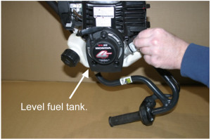
  • Position the 240H Hole Digger upright with the throttle control in contact with a suitable surface as depicted in FIGURE 1.
  • Hold the fuel tank level or parallel relative to the surface.
  • Remove the dipstick and check the oil level.
  • Replace the dipstick and secure finger tight.
eHelpNo13_img1

FIGURE 1. Note that fuel tank is positioned level or parallel relative with the surface.

Need help?
Call us at 800.533.0524, or
email: support@generalequip.com.

If excess oil flows from the crankcase, follow this procedure as described in the Owner’s
Manual provided by Honda:

Oil in the crankcase is difficult to remove; it cannot be pour or drained out…it must be
pumped out as the engine operates.

  • Replace the dipstick.
  • Position a shop towel under and around the engine spark plug to prevent oil from staining clothing and other personal property.
  • Remove the spark plug.
  • Pull the recoil starter and expect oil to rapidly exit the spark plug hole. Repeat this step until oil no longer exits. This will eliminate engine damage cause by hydro locking.
  • Replace the spark plug.
  • Drain oil from the crankcase until the oil just shows on the tip of the dipstick.
  • Run the engine for several minutes and then recheck the oil level.
  • If the oil level has increased, drain the excess oil so that the level is again just to the tip of the dipstick.
  • Repeat this procedure until the oil level no longer increases after the engine is run.
  • Replace the dipstick and secure finger tight.

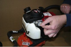
Do NOT check the oil level with the engine positioned as in FIGURE 2. This procedure can allow the crankcase to be filled with excess oil.

eHelpNo13_img2

FIGURE 2 depicting the improper method to check oil level for the Honda GX35 engine.

The correct oil capacity for the Honda GX35 engine is 100 cc or 3.4 fluid ounces. Refer to the Owner’s Manual supplied by Honda for additional information including type and weight. Service related problems, as a result of filling the engine with excessive oil, are NOT covered by Honda warranty program.

 If you have any questions or comments, please feel free to contact us.
Telephone: 800.533.0524 | Email: support@generalequip.com