How to Properly Repair FCS16 RIP-R-STRIPPER® Tile Stripper Extension Cords | Issue No. 21

How to Properly Repair FCS16 RIP-R-STRIPPER® Tile Stripper Extension Cords
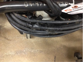
FIGURE 1. Improperly repaired

FIGURE 1. Improperly repaired

FCS16-1000A Extension Cord used with the FCS16 RIP-R-STRIPPER Tile Stripper improperly repaired. FIGURE 1.

In this case, it is presumed the RIP-R-STRIPPER Blade had come in contact with the extension cord and accidently cut it. Unfortunately, the Technician did not repair the cord according to National Electric Code practices by using the electrical tape. A replacement extension cord is expensive and you can save money by properly repairing a damaged cord.

 Need help?
Call us at 800.533.0524, or
email: support@generalequip.com.

Improper electrical cable splicing techniques can result in property damage and /or personal injury!


It is not legal to splice electrical extension cords.
Even if you solder the wire, wrap each wire with electrical tape and encase the whole splice in heat shrinkable tubing, it still will not have the abrasion resistance of a new cord. Plus, this practice is not permitted under the National Electric Code.
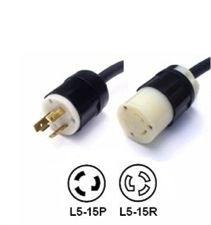
FIGURE 2.

FIGURE 2.

Instead, install a high quality NEMA L5-15P locking male plug and NEMA L5-15R locking female receptacle to the cut/severed extension cordends. These devices have a twist lock feature which will prevent them from separating when the extension cord is pulled around during normal tile stripping job applications. A typical NEMA L5-15P Locking Male Plug and a typical NEMA L5-15R Locking Female Receptacle are both depicted in FIGURE 2.

These electrical cable connecting devices are readily available in the field. Follow the installation instructions provided. Not using devices with the twist lock feature will allow the plug and receptacle to separate as the RIP-R-STRIPPER moves around on the jobsite.


Always follow repair procedures as specified by the current National Electric Code. Remember…safety is everyone’s responsibility!


If you have any questions or comments, please feel free to contact us.
Telephone: 800.533.0524 | Email: support@generalequip.com

Improper Throttle Cable Installation for the Two Man Auger | Issue No. 20

Improper Throttle Cable Installation for the Two Man Auger

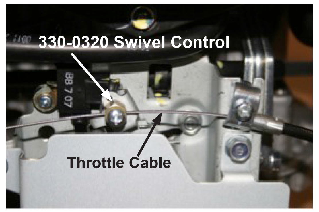
Improper throttle cable install can increase the potential for personal injury. FIGURE 1.

The throttle cable installation depicted will significantly reduce operator control while using the twist grip throttle system and could directly contribute to personal injury.

  1. Extended use of this installation can allow the throttle cable to be severed by the carburetor throttle mechanism leading and could directly contribute to personal injury.
  2. Correct installation will position and secure the Part Number 330-0320 Swivel Assembly in the hole provided on the carburetor throttle mechanism. The 330-0320 Swivel Control is designed to rotate as necessary to minimize throttle cable wear and provide for enhanced operator control. FIGURE 2.

To help reduce the potential for personal injury, it is critical for all throttle mechanism components be properly installed and maintained. The throttle control system must be inspected every time the Two Man Auger is turned. Refer to the applicable Tool Turning Tips publication for additional information. http://www.generalequip.com/Library. Form: GEF16101202.

Check your General hole digging equipment TODAY and every time tools are rented to determine the throttle cable is properly installed as outlined in the appropriate Operator Manual. Have questions or need help? Contact our Customer Service Department for assistance. 1.800.533.0524 or sales@generalequip.com

Remember: Safety is everyone’s responsibility!

Need help?
Call us at 800.533.0524, or
email: support@generalequip.com.

FIGURE 1. Improper Install

eHelp20p_ImgB

FIGURE 2. Proper Install

 If you have any questions or comments, please feel free to contact us.
Telephone: 800.533.0524 | Email: support@generalequip.com

New Changes in Two Man Auger Bits | Issue No. 19

New Changes in Two Man Auger Bits

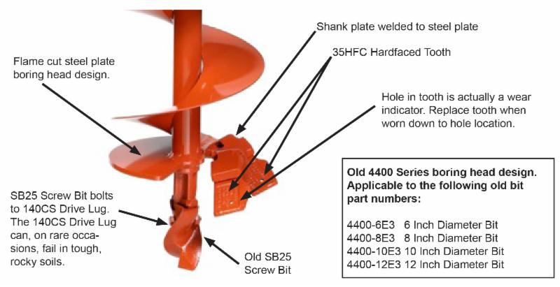
For 2014, there are changes in the bits that utilized with the General 330H Two Man Auger. These are the first significant change in the bit boring head design in over 50 years! This is an update to help provide further information to correctly order replacement parts.

New 4450 Series bits incorporate the following changes:

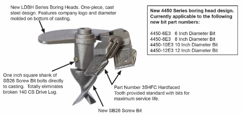
  • Eliminates the 140CS Drive Lug.
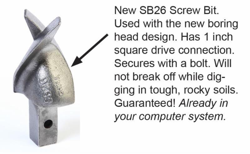
  • Replaces the SB25 Screw Bit with the new SB26 Screw Bit. The SB26 Screw Bit design eliminates any potential breakage from the 140CS Drive Lug.
  • Features a one piece, steel casting assembly with the specific bit diameter and General logo molded into it.
  • Sophisticated software was used to optimize tooth angle and position.
  • The new design better allows the bit to be more easily robotically welded. Robotic welding will increase manufacturing consistency and quality.

So…what’s the big deal? A bit is a bit. Right?

Well, the big deal is this: General is doing something different to manufacture a bit that digs better and lasts longer. The new 4450 Series bits are available in popular sizes: 6, 8, 10 and 12 inch diameter. Look for them beginning in February!


Need help?

Call us at 800.533.0524, or
email: support@generalequip.com.

Replacement wear part numbers for the 4450 Series Bits are as follows:

  • Teeth: Part Number 35HFC
  • Screw Bit: Part Number SB26
  • Bit Connecting Pin: Part Number 2121

Bit Part Number Information:

  • New 4450-6E3 6 Inch Diameter, Replaces 4400-6E3
  • New 4450-8E3 8 Inch Diameter, Replaces 4400-8E3
  • New 4450-10E3 10 Inch Diameter, Replaces 4400-10E3
  • New 4450-12E3 12 Inch Diameter, Replaces 4400-12E3
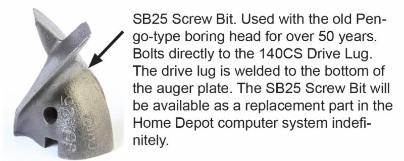
 Screw Bit Design Comparison

eHelp19p_ImgA

eHelp19p_ImgB


 New 4450 Series Bits

 eHelp19p_ImgC

Old 4400 Series Bits

eHelp19p_ImgD

If you have any questions or comments, please feel free to contact us.
Telephone: 800.533.0524 | Email: support@generalequip.com