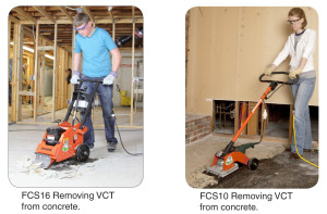

How to Properly Repair FCS16 RIP-R-STRIPPER® Tile Stripper Extension Cords
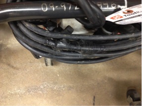
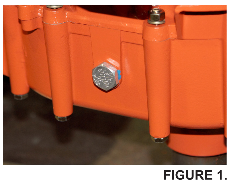
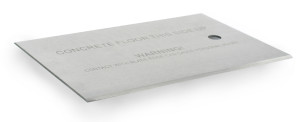
FIGURE 1. Improperly repaired
FCS16-1000A Extension Cord used with the FCS16 RIP-R-STRIPPER Tile Stripper improperly repaired. FIGURE 1.
In this case, it is presumed the RIP-R-STRIPPER Blade had come in contact with the extension cord and accidently cut it. Unfortunately, the Technician did not repair the cord according to National Electric Code practices by using the electrical tape. A replacement extension cord is expensive and you can save money by properly repairing a damaged cord.
Need help?
Call us at 800.533.0524, or
email: support@generalequip.com.
Improper electrical cable splicing techniques can result in property damage and /or personal injury!
It is not legal to splice electrical extension cords. Even if you solder the wire, wrap each wire with electrical tape and encase the whole splice in heat shrinkable tubing, it still will not have the abrasion resistance of a new cord. Plus, this practice is not permitted under the National Electric Code.
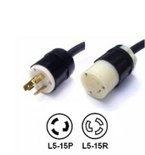
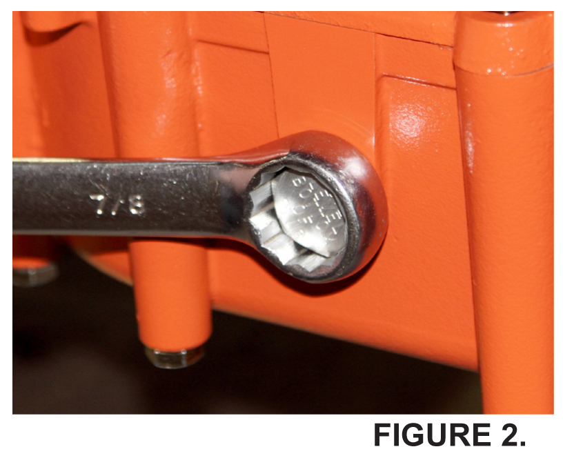
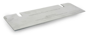
FIGURE 2.
Instead, install a high quality NEMA L5-15P locking male plug and NEMA L5-15R locking female receptacle to the cut/severed extension cordends. These devices have a twist lock feature which will prevent them from separating when the extension cord is pulled around during normal tile stripping job applications. A typical NEMA L5-15P Locking Male Plug and a typical NEMA L5-15R Locking Female Receptacle are both depicted in FIGURE 2.
These electrical cable connecting devices are readily available in the field. Follow the installation instructions provided. Not using devices with the twist lock feature will allow the plug and receptacle to separate as the RIP-R-STRIPPER moves around on the jobsite.
Always follow repair procedures as specified by the current National Electric Code. Remember…safety is everyone’s responsibility!
If you have any questions or comments, please feel free to contact us.
Telephone: 800.533.0524 | Email: support@generalequip.com